

En esta sección trataremos de explicar de la forma más clara posible, como montar un servidor web en NodeMcu devkit v0.9, con sensores y actuadores, programado en el Ide de Arduino
Si vives en Tenerife (Islas Canarias), no dudes en visitar la tienda de La Laguna 
En esta tienda he comprado el módulo NodeMcu devkit, gracias a ellos hoy podemos ver este tutorial.
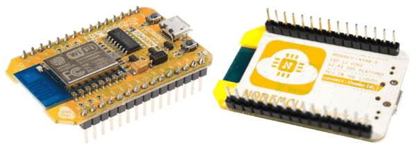
Este servidor está basado en NodeMcu devkit (ESP8266 ESP12), no será un servidor como el que muestra esta página que es una raspberry pi, para este trabajo el esp-12 y en general todos los esp se quedan pequeños. La función del servidor que vamos a crear será, informar bajo petición del estado de los sensores, y poder actuar sobre un relé en este caso. De esta manera tendremos un módulo económico, que se puede instalar en cualquier punto que tenga alcance nuestra red wifi, y facilitar de este modo el internet de las cosas.
Información sobre ESP8266 y modelos
La programación como hemos dicho será con el entorno de arduino si quieres saber como instalarlo y añadir soporte para los ESP8266, pásate por el siguiente enlace.
Instalar Ide de Arduino con soporte para ESP8266
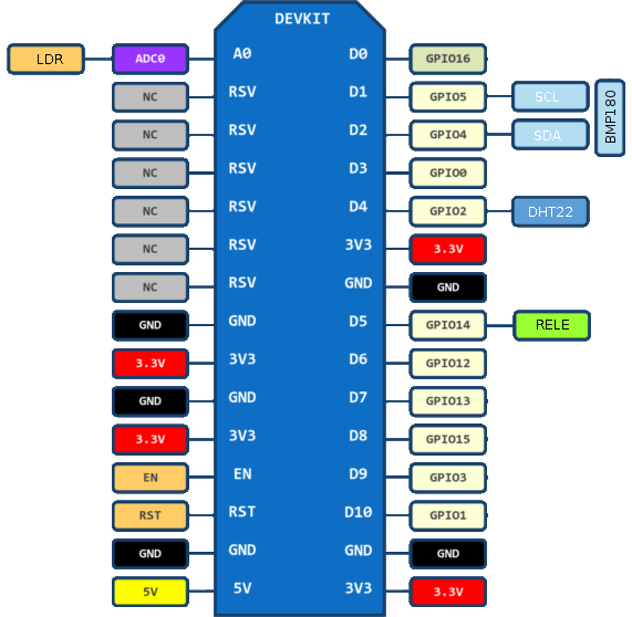
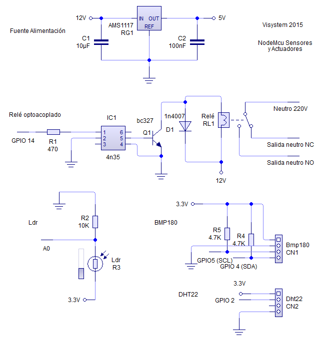
En la parte de sensores tendremos un ldr (sensor de luminosidad) conectado al pin analógico A0, un dht22 (sensor de temperatura y humedad) conectado al GPIO 2, y un bmp180 (sensor de presión barométrica y temperatura) conectado a los GPIOs 4 y 5. En la parte de actuadores tendremos un relé conectado al GPIO, 14.
Comenzamos el montaje, lo haremos por partes para evitar problemas y poder probar cada sensor actuador por separado.
El primer paso será montar la fuente de alimentación (en este caso, se ha montado la fuente de alimentación, porque vamos a utilizar un transformador de corriente continua de 12 voltios, si se alimenta a 5 voltios podemos prescindir de la fuente) y realizar el circuito para conectar el relé, luego programaremos el servidor que permita interactuar con él, partiremos del siguiente circuito.
Información adicional de relés aquí
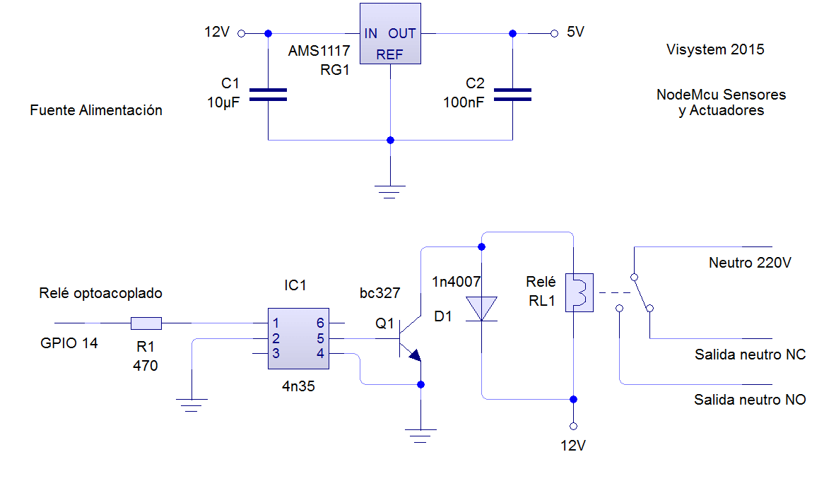
El código para la programación en el Ide de arduino es el siguiente, de momento no necesitaremos ninguna librería adicional, es uno de los ejemplos incluidos en el ide de arduino adaptado el gpio, en este caso el relé será controlado por el GPIO14.
/* * This sketch demonstrates how to set up a simple HTTP-like server. * The server will set a GPIO pin depending on the request * http://server_ip/rele/0 will set the GPI14 low, * http://server_ip/rele/1 will set the GPI14 high * server_ip is the IP address of the ESP8266 module, will be * printed to Serial when the module is connected. */ #includeconst char* ssid = "your-ssid"; const char* password = "your-password"; // Create an instance of the server // specify the port to listen on as an argument WiFiServer server(80); void setup() { Serial.begin(115200); delay(10); // prepare GPIO14 pinMode(14, OUTPUT); digitalWrite(14, 0); // Connect to WiFi network Serial.println(); Serial.println(); Serial.print("Connecting to "); Serial.println(ssid); WiFi.begin(ssid, password); while (WiFi.status() != WL_CONNECTED) { delay(500); Serial.print("."); } Serial.println(""); Serial.println("WiFi connected"); // Start the server server.begin(); Serial.println("Server started"); // Print the IP address Serial.println(WiFi.localIP()); } void loop() { // Check if a client has connected WiFiClient client = server.available(); if (!client) { return; } // Wait until the client sends some data Serial.println("new client"); while(!client.available()){ delay(1); } // Read the first line of the request String req = client.readStringUntil('\r'); Serial.println(req); client.flush(); // Match the request int val; if (req.indexOf("/rele/0") != -1) val = 0; else if (req.indexOf("/rele/1") != -1) val = 1; else { Serial.println("invalid request"); client.stop(); return; } // Set GPIO2 according to the request digitalWrite(14, val); client.flush(); // Prepare the response String s = "HTTP/1.1 200 OK\r\nContent-Type: text/html\r\n\r\n\r\n<html>\r\nEl rele esta "; s += (val)?"activado":"desactivado"; s += "</html>\n"; // Send the response to the client client.print(s); delay(1); Serial.println("Client disonnected"); // The client will actually be disconnected // when the function returns and 'client' object is detroyed }
Ahora si todo a salido bien, ya podemos entrar al servidor desde cualquier navegador de nuestra red local, para ello debemos introducir la dirección ip asignada a nuestro Nodemcu (podemos ver la ip asignada si tenemos conectado el Nodemcu al puerto serie), luego si queremos apagar el relé introducimos rele/0 y para encenderlo rele/1.
Ejemplo si el nodemcu tiene la ip 192.168.1.175, entramos a la dirección 'http://192.168.1.175/rele/0' para apagar el relé y 'http://192.168.1.175/rele/1' para encenderlo.

El siguiente montaje que vamos a realizar es el del sensor ldr, para ello seguiremos el siguiente esquema, como vemos nuestra sensor ldr está conectado al único pin analógico disponible A0.
Información adicional del sensor ldr aquí
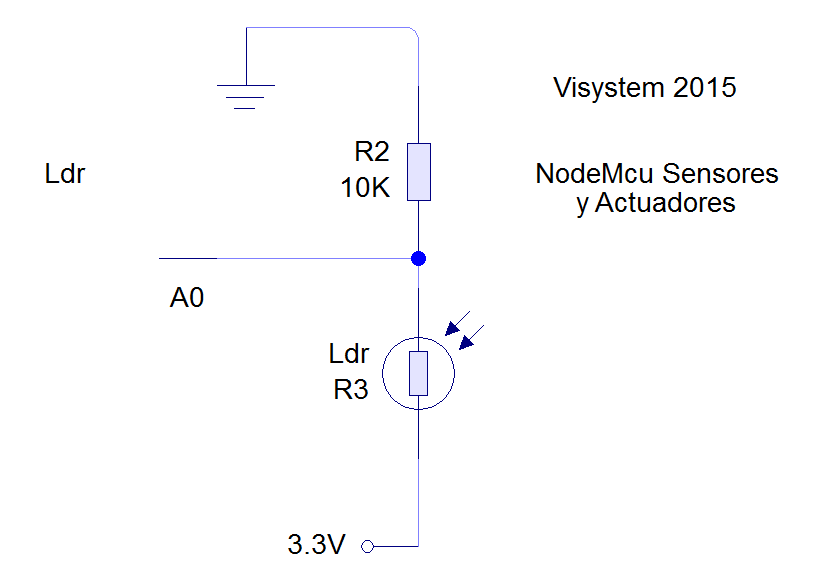
El siguiente código para el Ide de arduino incluye el relé y el ldr además del servidor para intectuar con ambos, de momento no necesitamos librerías adicionales.
/* * This sketch demonstrates how to set up a simple HTTP-like server. * The server will set a GPIO pin depending on the request * http://server_ip/rele/0 will set the GPI14 low, * http://server_ip/rele/1 will set the GPI14 high * http://server_ip/ldr/ will ldr value * server_ip is the IP address of the ESP8266 module, will be * printed to Serial when the module is connected. */ #includeconst char* ssid = "your-ssid"; const char* password = "your-password"; // Create an instance of the server // specify the port to listen on as an argument WiFiServer server(80); int valoranalogica=0; int selector=0; String salida; void setup() { Serial.begin(115200); delay(10); // prepare GPIO14 pinMode(14, OUTPUT); digitalWrite(14, 0); // Connect to WiFi network Serial.println(); Serial.println(); Serial.print("Connecting to "); Serial.println(ssid); WiFi.begin(ssid, password); while (WiFi.status() != WL_CONNECTED) { delay(500); Serial.print("."); } Serial.println(""); Serial.println("WiFi connected"); // Start the server server.begin(); Serial.println("Server started"); // Print the IP address Serial.println(WiFi.localIP()); } void loop() { valoranalogica=analogRead(A0); // Check if a client has connected WiFiClient client = server.available(); if (!client) { return; } // Wait until the client sends some data Serial.println("new client"); while(!client.available()){ delay(1); } // Read the first line of the request String req = client.readStringUntil('\r'); Serial.println(req); client.flush(); // Match the request int val; if (req.indexOf("/rele/0") != -1){ digitalWrite(14, 0); val = 0; selector=1; } else if (req.indexOf("/rele/1") != -1){ digitalWrite(14, 1); val =1; selector=1; } else if (req.indexOf("/ldr") != -1){ selector=2; } else { Serial.println("invalid request"); client.stop(); return; } client.flush(); // Prepare the response salida = "HTTP/1.1 200 OK\r\nContent-Type: text/html\r\n\r\n\r\n<html>\r\n"; if (selector ==1){ salida += "Rele está ahora: "; salida += (val)?"activado":"descativado"; } if (selector ==2){ salida += "Valor de ldr: "; salida += (valoranalogica); } salida += "</html>\n"; selector=0; // Send the response to the client client.print(salida); delay(1); Serial.println("Client disonnected"); // The client will actually be disconnected // when the function returns and 'client' object is detroyed }
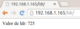
Nuevamente si todo a salido bien ya podemos ver el valor leído por nuestro sensor ldr entrado a la dirección 'http://ip_asignada/ldr/'.
Para el montaje del sensor dht22,seleccionaremos el GPIO 2 y seguiremos el siguiente esquema.
Información adicional del sensor dht22 aquí

Para la programción en el ide de arduino vamos a necesitar la librería para el sensor dht22 y el siguiente código, con él tendremos el relé, el ldr y el dht22 montado en un servidor para interactuar.
Descargar librería Dht22 de Arduino para Esp8266/* * This sketch demonstrates how to set up a simple HTTP-like server. * The server will set a GPIO pin depending on the request * http://server_ip/rele/0 will set the GPI14 low, * http://server_ip/rele/1 will set the GPI14 high * http://server_ip/ldr/ will ldr value * http://server_ip/dht22/ will dht22 value * server_ip is the IP address of the ESP8266 module, will be * printed to Serial when the module is connected. */ #include "DHT.h" #define DHTPIN 2 // what pin we're connected to // Uncomment whatever type you're using! //#define DHTTYPE DHT11 // DHT 11 #define DHTTYPE DHT22 // DHT 22 (AM2302) //#define DHTTYPE DHT21 // DHT 21 (AM2301) // Connect pin 1 (on the left) of the sensor to +3.3V // Connect pin 2 of the sensor to whatever your DHTPIN is // Connect pin 4 (on the right) of the sensor to GROUND DHT dht(DHTPIN, DHTTYPE,20); float h, t; #includeconst char* ssid = "your-ssid"; const char* password = "your-password"; // Create an instance of the server // specify the port to listen on as an argument WiFiServer server(80); int valoranalogica=0; int selector=0; String salida; const long interval = 2000; unsigned long tiempo_pasado=0; void setup() { Serial.begin(115200); // prepare GPIO2 for DHT22 pinMode(2,INPUT); digitalWrite(2,HIGH); delay(10); dht.begin(); // prepare GPIO14 pinMode(14, OUTPUT); digitalWrite(14, 0); // Connect to WiFi network Serial.println(); Serial.println(); Serial.print("Connecting to "); Serial.println(ssid); WiFi.begin(ssid, password); while (WiFi.status() != WL_CONNECTED) { delay(500); Serial.print("."); } Serial.println(""); Serial.println("WiFi connected"); // Start the server server.begin(); Serial.println("Server started"); // Print the IP address Serial.println(WiFi.localIP()); } void loop() { valoranalogica=analogRead(A0); unsigned long currentMillis = millis(); if(currentMillis - tiempo_pasado >= interval) { h = dht.readHumidity(); t = dht.readTemperature(); if (isnan(t) || isnan(h)) { Serial.println("Fallo al leer sensor DHT22"); } tiempo_pasado = currentMillis; } // Check if a client has connected WiFiClient client = server.available(); if (!client) { return; } // Wait until the client sends some data Serial.println("new client"); while(!client.available()){ delay(1); } // Read the first line of the request String req = client.readStringUntil('\r'); Serial.println(req); client.flush(); // Match the request int val; if (req.indexOf("/rele/0") != -1){ digitalWrite(14, 0); val = 0; selector=1; } else if (req.indexOf("/rele/1") != -1){ digitalWrite(14, 1); val =1; selector=1; } else if (req.indexOf("/ldr") != -1){ selector=2; } else if (req.indexOf("/dht22") != -1){ selector=3; } else { Serial.println("invalid request"); client.stop(); return; } client.flush(); // Prepare the response salida = "HTTP/1.1 200 OK\r\nContent-Type: text/html\r\n\r\n\r\n<html>\r\n"; if (selector ==1){ salida += "Rele esta ahora: "; salida += (val)?"activado":"desactivado"; } if (selector ==2){ salida += "Valor de ldr: "; salida += (valoranalogica); } if (selector ==3){ salida += "Temperatura: "; salida += (t); salida += " Humedad: "; salida += (h); } salida += "</html>\n"; selector=0; // Send the response to the client client.print(salida); delay(1); Serial.println("Client disonnected"); // The client will actually be disconnected // when the function returns and 'client' object is detroyed }
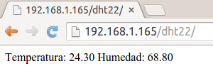
Si todo a salido bien ya podemos ver los datos obtenidos del sensor dht22 entrado a la dirección 'http://ip_asignada/dht22/'.
Para el montaje del sensor bmp180, como el esp-12 no tiene Gpio hardware para el bus I2c, seleccionaremos el GPIO 4 como SDA y el GPIO 5 como SCL, seguiremos el siguiente esquema.
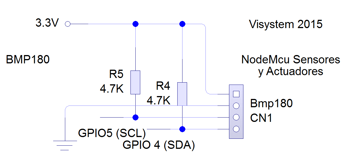
Información adicional del sensor bmp180 aquí
Para la programción en el ide de arduino vamos a necesitar la librería para el sensor bmp180, la librería para el dht22 y el siguiente código.
Descargar librería bmp180 de Arduino para Esp8266 Descargar librería Dht22 de Arduino para Esp8266Este sketck incluye el relé, y los sensores: ldr, bmp180 y dth22 con el servidor para interactuar con ellos.
/* * This sketch demonstrates how to set up a simple HTTP-like server. * The server will set a GPIO pin depending on the request * http://server_ip/rele/0 will set the GPI14 low, * http://server_ip/rele/1 will set the GPI14 high * http://server_ip/ldr/ will ldr value * http://server_ip/dht22/ will dht22 value * http://server_ip/bmp180/ will bmp180 value * server_ip is the IP address of the ESP8266 module, will be * printed to Serial when the module is connected. */ #include#include int sensorbmp=1; #define I2C_SCL 5 // Barometric Pressure Sensor (BMP085) #define I2C_SDA 4 // Barometric Pressure Sensor (BMP085) Adafruit_BMP085 bmp; #include "DHT.h" #define DHTPIN 2 // what pin we're connected to // Uncomment whatever type you're using! //#define DHTTYPE DHT11 // DHT 11 #define DHTTYPE DHT22 // DHT 22 (AM2302) //#define DHTTYPE DHT21 // DHT 21 (AM2301) // Connect pin 1 (on the left) of the sensor to +3.3V // Connect pin 2 of the sensor to whatever your DHTPIN is // Connect pin 4 (on the right) of the sensor to GROUND DHT dht(DHTPIN, DHTTYPE,20); float h, t; #include const char* ssid = "your-ssid"; const char* password = "your-password"; // Create an instance of the server // specify the port to listen on as an argument WiFiServer server(80); int valoranalogica=0; int selector=0; String salida; const long interval = 2000; unsigned long tiempo_pasado=0; void setup() { Serial.begin(115200); // prepare GPIO2 for DHT22 pinMode(2,INPUT); digitalWrite(2,HIGH); delay(10); dht.begin(); // prepare GPIO14 pinMode(14, OUTPUT); digitalWrite(14, 0); if (!bmp.begin()) { Serial.println("No se puede encontar el sensor BMP085, comprueba conexión!"); sensorbmp=0; } // Connect to WiFi network Serial.println(); Serial.println(); Serial.print("Connecting to "); Serial.println(ssid); WiFi.begin(ssid, password); while (WiFi.status() != WL_CONNECTED) { delay(500); Serial.print("."); } Serial.println(""); Serial.println("WiFi connected"); // Start the server server.begin(); Serial.println("Server started"); // Print the IP address Serial.println(WiFi.localIP()); } void loop() { valoranalogica=analogRead(A0); unsigned long currentMillis = millis(); if(currentMillis - tiempo_pasado >= interval) { h = dht.readHumidity(); t = dht.readTemperature(); if (isnan(t) || isnan(h)) { Serial.println("Fallo al leer sensor DHT22"); } tiempo_pasado = currentMillis; } // Check if a client has connected WiFiClient client = server.available(); if (!client) { return; } // Wait until the client sends some data Serial.println("new client"); while(!client.available()){ delay(1); } // Read the first line of the request String req = client.readStringUntil('\r'); Serial.println(req); client.flush(); // Match the request int val; if (req.indexOf("/rele/0") != -1){ digitalWrite(14, 0); val = 0; selector=1; } else if (req.indexOf("/rele/1") != -1){ digitalWrite(14, 1); val =1; selector=1; } else if (req.indexOf("/ldr") != -1){ selector=2; } else if (req.indexOf("/dht22") != -1){ selector=3; } else if (req.indexOf("/bmp") != -1){ selector=4; } else { Serial.println("invalid request"); client.stop(); return; } client.flush(); // Prepare the response salida = "HTTP/1.1 200 OK\r\nContent-Type: text/html\r\n\r\n\r\n<html>\r\n"; if (selector ==1){ salida += "Rele esta ahora: "; salida += (val)?"activado":"desactivado"; } if (selector ==2){ salida += "Valor de ldr: "; salida += (valoranalogica); } if (selector ==3){ salida += "Temperatura: "; salida += (t); salida += " Humedad: "; salida += (h); } if (selector ==4){ if (sensorbmp ==1){ salida += "Temperatura: "; salida += (bmp.readTemperature()); salida += " Presion: "; salida += (bmp.readPressure()); } } salida += "</html>\n"; selector=0; // Send the response to the client client.print(salida); delay(1); Serial.println("Client disonnected"); // The client will actually be disconnected // when the function returns and 'client' object is detroyed }
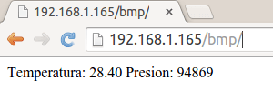
Si todo a salido bien ya podemos ver los datos obtenidos del sensor bmp180 entrado a la dirección 'http://ip_asignada/bmp/'.
En la siguiente imagen pueden ver que gpios se han asignado a los sensores/actuadores del servidor.
En la siguiente imagen pueden ver el esquema completo de los sensores y actuadores montados en el servidor.
Para finalizar unas fotos del prototipo que he montado.
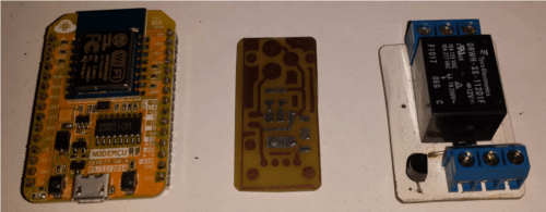
En esta foto podemos ver el Nodemcu, junto al pcb de la fuente de alimentación y el réle, montado ya en pcb.
En esta vemos la parte interior con los elementos que la componen.
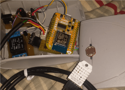
En esta podemos ver el prototipo montado en su caja, con el dht22 y el ldr al exterior, el relé y el bmp180 están dentro de la caja.
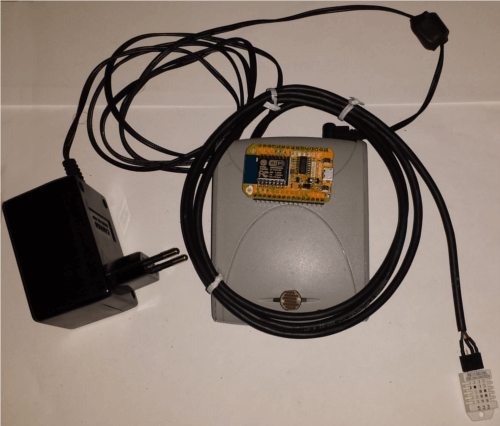
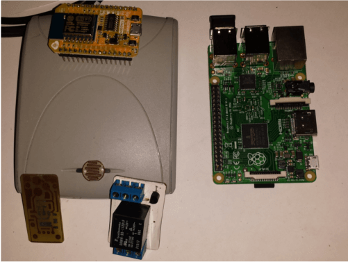
Para finalizar, una imagen para comparar el tamaño del servidor montado a la Raspberry Pi 2.
Y esto ha sido todo, espero que les haya gustado y sobre todo que les sea útil.